AUTODESK MOLDFLOW INSIGHT

Autodesk® Moldflow® is a plastic injection analysis software used to simulate the injection process, detect potential manufacturing defects in plastic parts in advance, and make necessary changes in part design, mold design, and process parameters before production to eliminate these issues.

With its patented Dual Domain™ technology, Autodesk® Moldflow® simulates the plastic injection process quickly and accurately, ensuring that potential problems in part and mold design are resolved before the manufacturing stage.

Thanks to the advanced material database, plastic part and mold designers can easily access the material information they need. With Autodesk® Moldflow®, it is possible to perform the following analyses:

  • Thermoplastics Injection Molding
  • Thermoplastics Overmolding
  • Gas-Assisted Injection Molding
  • Co-Injection Molding
  • Injection-Compression Molding
  • Reactive Injection-Compression Molding
  • Reactive Molding
  • Multiple-Barrel Reactive Molding
  • Microchip Encapsulation
  • RTM/SRIM
  • Underfill Encapsulation

Analyses That Can Be Performed with Autodesk® Moldflow® Insight:

Plastic Flow Analysis:

Used to simulate filling and packing processes in plastic injection and to determine optimal process parameters. With plastic flow analysis:

  • The optimal mold temperature and plastic melt temperature can be determined.
  • Filling time and filling profile can be optimized.
  • Packing time and packing profile can be optimized.
  • The maximum injection pressure and clamping force required to mold the part can be determined.
  • Potential weld lines, air traps, and sink marks during injection can be identified.
  • Material usage can be optimized.
  • Improvements can be made in part and runner system design.
  • Automatic runner balancing can be performed, ensuring all mold cavities fill simultaneously and at the same pressure.
  • Hot and cold runner systems can be analyzed.
  • Multi-cavity molds can be analyzed.
  • Valve gate analysis can be performed for hot runner systems.
  • The optimal gate location can be determined.
  • Optimal injection parameters can be found based on part geometry, gate location, material, surface quality, and injection pressure.

Finding the Optimal Gate Location

Filling Analysis

Runner Balancing

Valve Gate Analysis

Mold Cooling Analysis (Cooling Simulation):

With Autodesk® Moldflow® Insight, heat transfer events inside the mold during the plastic injection process can be simulated to determine the necessary process parameters for optimal mold cooling and to design cooling components. With cooling analysis:

  • The optimal cooling time of the mold can be determined.
  • Mold and part design can be optimized to achieve the shortest cycle time and a uniform temperature distribution on the part.
  • Temperature distribution on the plastic part, mold, cooling channels, inserts, and runners can be determined.
  • Hot and cold spots on the part can be identified.
  • Uneven cooling and residual stresses can be minimized to reduce warpage.
  • Temperature differences between the core and cavity mold cores can be determined.

While performing cooling analysis in Autodesk® Moldflow®, the following cooling components can be designed:

  • Cooling Channels
  • Inserts
  • Baffles
  • Bubblers
  • Hoses

Warpage Analysis (Warpage Simulation):

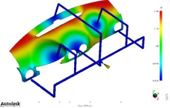
With Autodesk® Moldflow®, warpage in a plastic part can be analyzed before the part is manufactured, and the causes of the warpage can be identified and corrected. With warpage analysis:

  • The distribution of warpage and shrinkage on the part can be seen before the mold is manufactured.
  • It can be determined whether the warpage is within design tolerances using advanced warpage visualization tools.
  • Warpage in the X, Y, and Z directions, as well as total warpage, can be observed separately.
  • The distance between two selected points on the part can be measured to check if it remains within tolerances after manufacturing.
  • The causes of warpage (uneven cooling, shrinkage, material and fiber orientation, etc.) and their impact on total warpage can be determined.
  • Warpage results can be exported as STL files to CAD programs.

Visualization of warpage results

Identification of factors causing warpage

Core-Shift Analysis:

During injection, the deformation of thin and long cores can be calculated, and as a result of these deformations, the thickness variations on the plastic part can be determined to check whether the design tolerances are exceeded.

Fiber Orientation Analysis:

With Autodesk® Moldflow®, the fiber distribution resulting from the injection of fiber-reinforced plastics can be analyzed. With fiber analysis:

  • The distribution and orientation of fibers on the plastic part can be determined.
  • The distribution of the part’s thermo-mechanical properties after injection can be assessed.
  • The distribution of the modulus of elasticity can be analyzed.
  • The distribution of the coefficient of thermal expansion can be determined.
  • The distribution of Poisson’s ratio can be evaluated.
  • The fiber distribution can be optimized to reduce warpage and shrinkage in the part.

Autodesk® Moldflow® material library includes a variety of additives for reinforced plastics, such as:

  • Glass fibers
  • Carbon fibers
  • Aramid fibers
  • Asbestos fibers
  • Boron fibers
  • Metals
  • Minerals

The thermo-mechanical properties obtained from the analysis can be exported to other structural analysis programs (ANSYS, ABAQUS).

Stress Analysis:

The deformation of a plastic part and the stresses that occur under applied mechanical and thermal loads can be calculated. The analysis uses the distribution of mechanical properties obtained from the plastic injection process, enabling more realistic results. The types of analysis that can be performed include:

  • Linear stress analysis
  • Natural frequency analysis
  • Linear buckling analysis
  • Nonlinear stress analysis

Shrink Analysis:

Using the values obtained from filling and packing analysis, the shrinkage distribution on the plastic part is calculated. With shrinkage analysis:

  • It provides a single shrinkage value for the plastic part.
  • Shrinkage values can be determined separately in the X, Y, and Z directions.
  • It is the only software that calculates shrinkage independently of warpage analysis.
  • The analysis shows whether the specified dimensions remain within tolerances and determines how much they deviate from the tolerances.